I would thank Qualtex Irl, for their initial guidance. I would also caution anyone considering the following detail, you require a mechanical aptitude and have background experience in electronics to effect a complete repair.
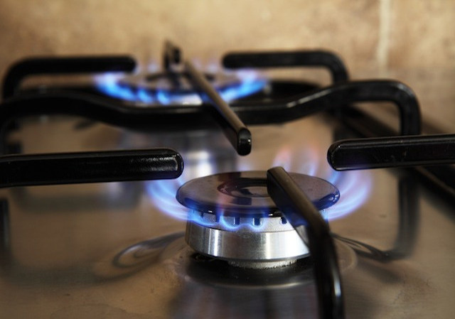
The solution. Having removed the cooker side panels, three screws for each side panel at the back of the cooker, and two at the front edge, one each located on the inside front edge of the grill and oven apertures, you then need to very carefully remove the "L" shaped brown plastic inserts at the end of the glass control panel, use a very thin, sharp blade to prise them out, this will give access to the plastic end plate fixing screws. Undo the three visible screws which hold the plastic end plates to the control unit and cooker body, and also one screw which is beneath the front edge of the control panel (open the grill door, and look up). You now have the cooker with its side panels off, and the plastic end plates removed from the glass control panel. To remove the glass control panel, gently pull each of the hob control knobs up and off, and, from the oven control area of the glass panel, gently pull up, and remove each of the eight selector buttons, and also pull the data selector knob off the shaft of the oven control module. The glass control panel is still held in place by means of a groove in the front edge of the control panel assembly, and the leading edge of the halogen hob unit, which bears down on the glass control panel. To complete the glass control panel removal, loosen/remove the four lowest screws, two at each side, which hold the halogen hob assembly to the top of the cooker body, and lift the front edge of the halogen hob assembly, where it is bearing on the glass control panel. There is an adhesive sealing strip here, so it may be a little difficult, and try not to damage the sealing strip. Once you have lifted the front edge of the halogen hob assembly clear of the glass control panel, by about a inch or so, place a length of wood beneath the hob assembly, between the underside of the hob assembly and the top of the cooker body, to keep the hob metal frame in position, and clear of the glass control panel. You are now in a position to remove the glass control panel by lifting the glass panel by the top left/right hand corner edges until the data control shaft is clear of the glass panel, then simply lift the glass panel out of the front edge groove. There is another sealing strip, in the front edge of the control panel.......
You can now gain access to the electronic oven control module, which was manufactured by DIEHL in Germany, and their type reference is 317/1 T85. The display indicator is by Futaba, and is type 8-LT-24ZA/7B.
The fault with my oven controller was that it would not set the time and the oven control would not work, but the display kept "flashing" from side to side, as though there had been a power cut.....So, grip the oven control module on both sides and pull it up as far as possible, this will allow access to the cables/connectors beneath. Proceeding across the back of the module, tie a thin cord, in a "daisy chain" to each of the connector wires, this means you will not "lose" any!......also, as a back up, draw an accurate diagram which the shows the colours of the wires, and where each connector was fitted at the rear of the module. Remove each "flying" connector by pulling the female connectors from the blades, and lift the electronic oven control module clear of the cooker control panel. In my case, to access the internal electronics of the faulty oven control module....using a Stanley knife, gently slip the blade along each edge of the oven control module red coloured front panel, this will allow the coloured insert to "pop" out of the black body of the module. Remove the three screws situated amongst the connector blades at the rear of the module, and by using strips of credit cards as wedges, and a small screwdriver as a lever, gently, and very carefully, ease out the two printed circuit boards which form the oven control unit. The boards are held in by means of small plastic protrusions on the inside of the module casing and they are a tight fit.........having now removed the two printed circuit boards, one being the power supply and the other, with the Futaba display, being the control board, using a new/clean one inch paint brush, remove any dust etc. and examine the boards for signs of over heated copper tracks/components etc. in my case there were none. Now to proceed further, you need to be familiar with electronic repairs.....you can power the oven control module on the bench, and in so doing, check the operation of the unit. In my case, with the oven control module powered and on the bench, I found that gently probing the components on the control board with a plastic knitting needle, revealed an intermittent soldered joint, that is, gentle pressure applied to the faulty connection caused the oven control module to resume normal operation, a "classic" "dry joint" problem with printed circuit assemblies!......my solution, was to carefully resolder the discovered intermittent joint, and then, as a precaution, resolder every other soldered joint on the control board , using a temperature controlled soldering iron and low melting point solder. Re-assembly of the oven control module is to carefully replace the two printed circuit boards into the module casing, ensuring that the two mechanical couplings between the boards are in the correct position, and then, gently press them into position, until you hear the "click" of the module case fixings, replace the three fixing screws, and then press the red coloured front insert into position......
The result, the oven control module is now working and reinstalled. My Tricity Sovereign 4638 is back in working order, just the repair of one defective soldered joint, in the electronic oven controller module, saved me the cost of a replacement cooker to the same specification.
If I had had the benefit of the above detail, then the work could have been completed in a few hours.
I also took the opportunity to replace both the flourescent tube and starter for the control panel illumination, whilst I had
access to the depths of the control panel.
A request....If anyone reading this has spare brown halogen hob control knob for the Tricity Sovereign 4638, I am in need of one.
John
May 2008
 howtomendit.com for free repair help, information and advice.